This work is supported by the European Union’s European Research Council (ERC) Starting Grant under the grant agreement 101116162–0-drift–ERC-2023-STG.
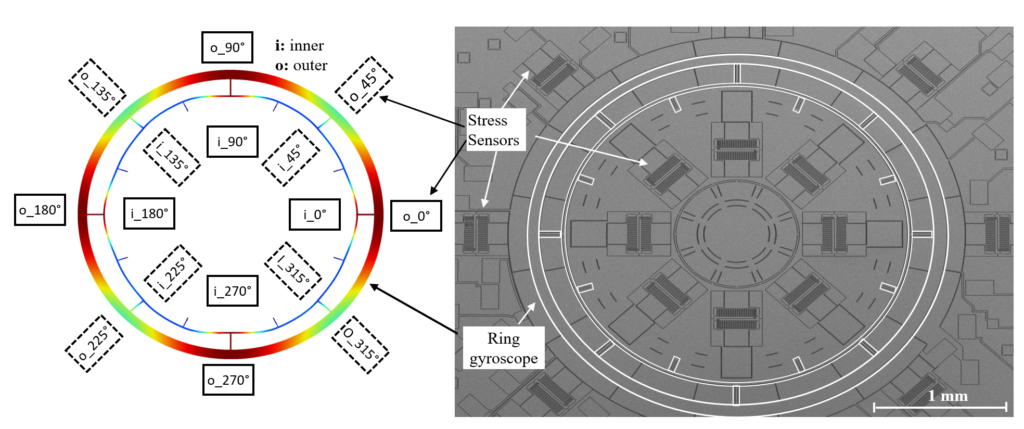
Autonomous navigation will be an indispensable part of our lives in the near future. Data from multiple sensors, i.e., GPS, camera, LIDAR, RADAR, and inertial sensors are fused in the navigation algorithms. Unlike any other modality, inertial navigation, which integrates the acceleration and rotation data to track position, is error and jamming-free if a no-drift sensor could be invented. MEMS sensors enable widespread cost-effective inertial navigation, but MEMS sensor drift limits position accuracy as small inherent measurement errors accumulate over time. Our goal is to address the MEMS sensor drift problem by integrating on-chip distributed stress sensors with the MEMS sensors. This advanced approach enables us to capture MEMS sensor drift at its source and calibrate the drift.
Our research spans all areas of MEMS research:
Design of the MEMS inertial sensors; gyroscopes and accelerometers, and on-chip stress sensors
Microfabrication of the sensors (7-14 masks)
Design of discrete and integrated electronics (ASIC)
Development of the control algorithms
Sensor characterization
Analytical modeling of the drift mechanisms
Development of the drift-calibration algorithms
Architecture of the MEMS gyroscope with on-chip stress sensors
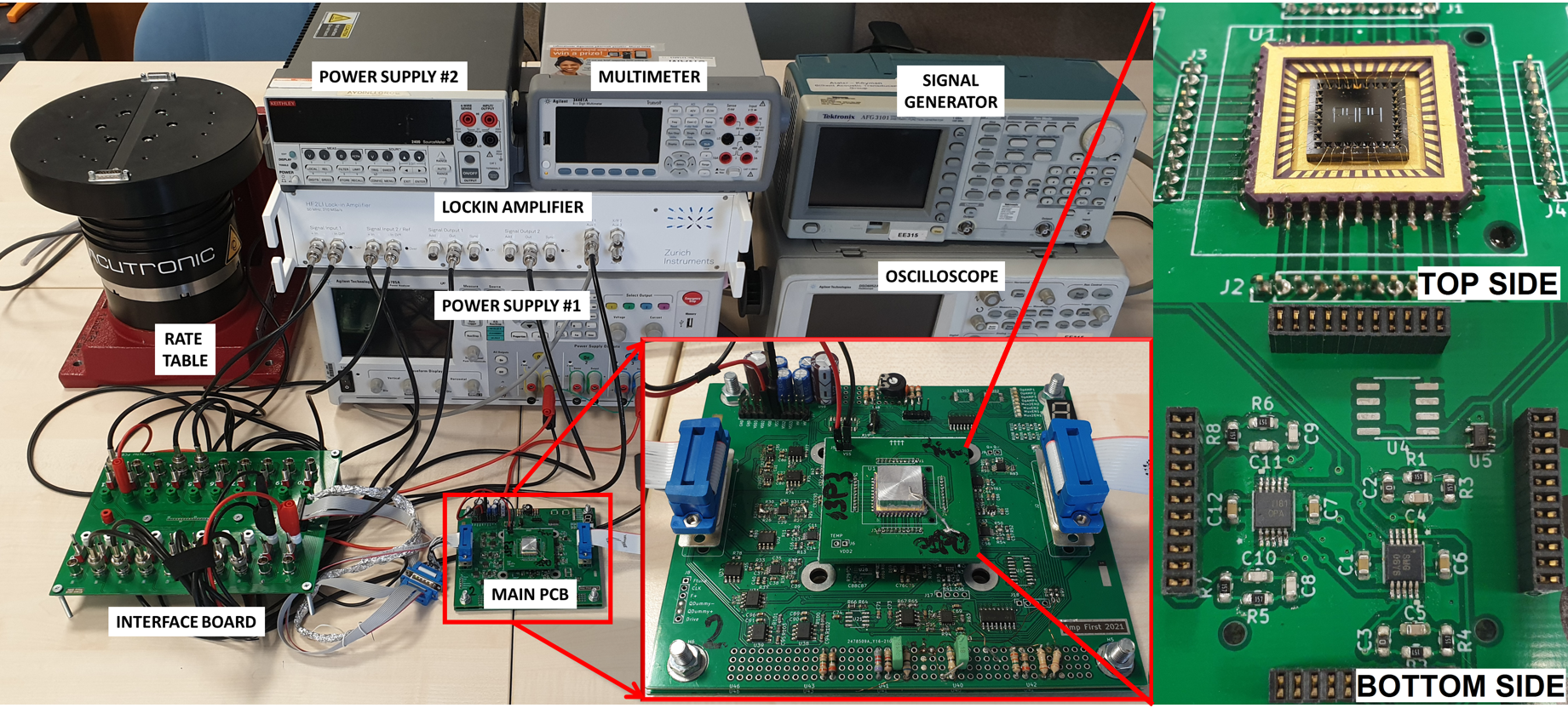
Below is a picture of the overall test setup when MEMS sensor and the electronics are connected. The system is quite complex, consisting of front end amplifiers, multiplexers for the stress sensor reading, signal conditioning amplifiers and multiple control loops.
Overall test setup when MEMS and electronics are connected
Stress Sensors
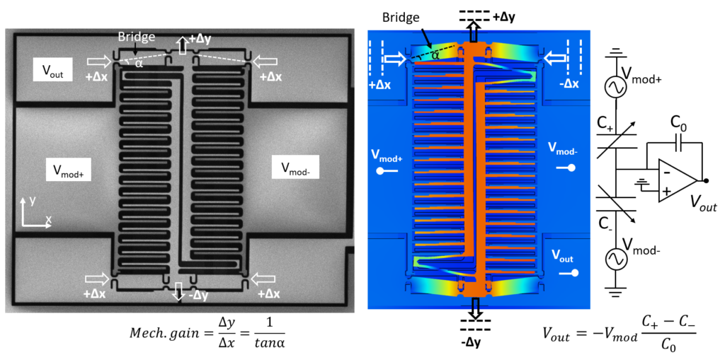
We measure stress with capacitive stress sensors that amplify the substrate strain and convert it to capacitance.
Capacitive stress sensor, the substrate strain is amplified by the bridge and converted into capacitance
What can be achieved with stress calibration?
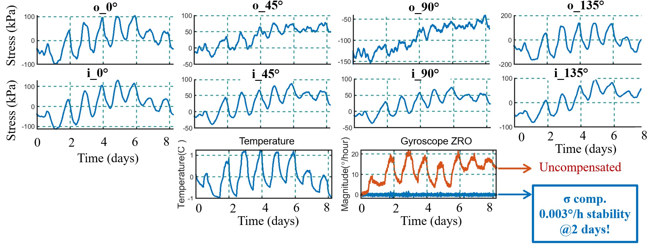
A 8-day long-term stability test with stress calibration shows a 0.003°/h bias instability with no signs of drift.
Long term stability test at room temperature
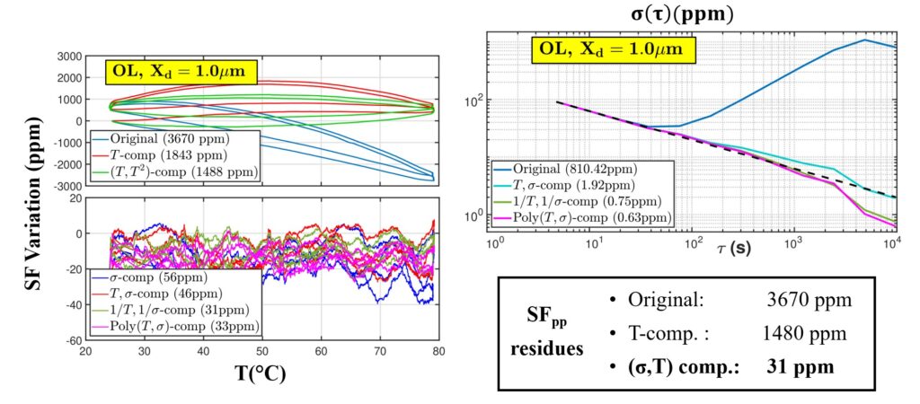
30 ppm scale factor variation over 60°C temperature cycling, >40X improvement over the temperature calibration.
Scale factor variation over temperature
Analytical Modeling
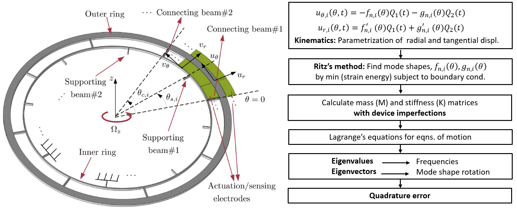
An effective drift calibration requires a deep understanding of the drift dynamics. We develop analytical models that predict the gyroscope parameters, i.e., stiffness, quadrature error, and zero rate output (ZRO) with process imperfections, stress, and temperature. These models constitute the fundamental building block of physics-aware on-chip stress calibration which is our ultimate goal.
The first step is figuring out the device imperfections and finding the mode shapes of the structure.
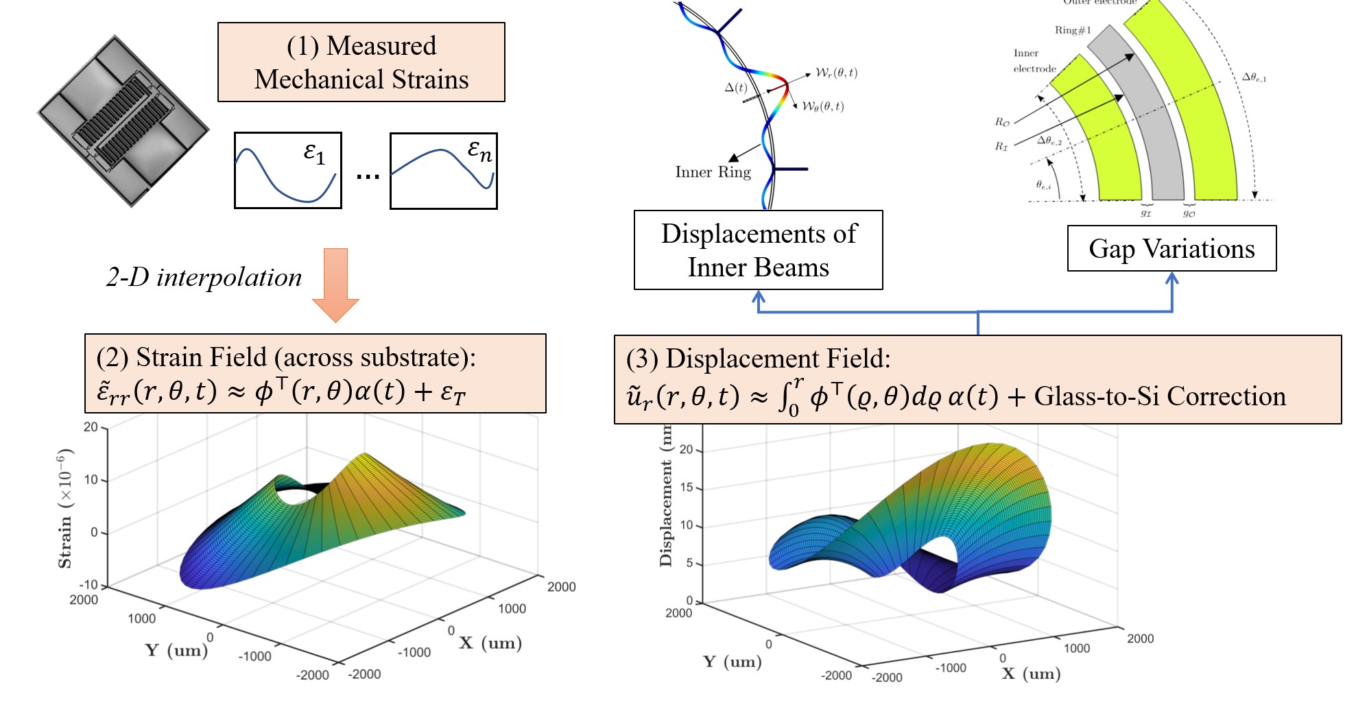
We then perform a strain interpolation using the on-chip stress sensor data.
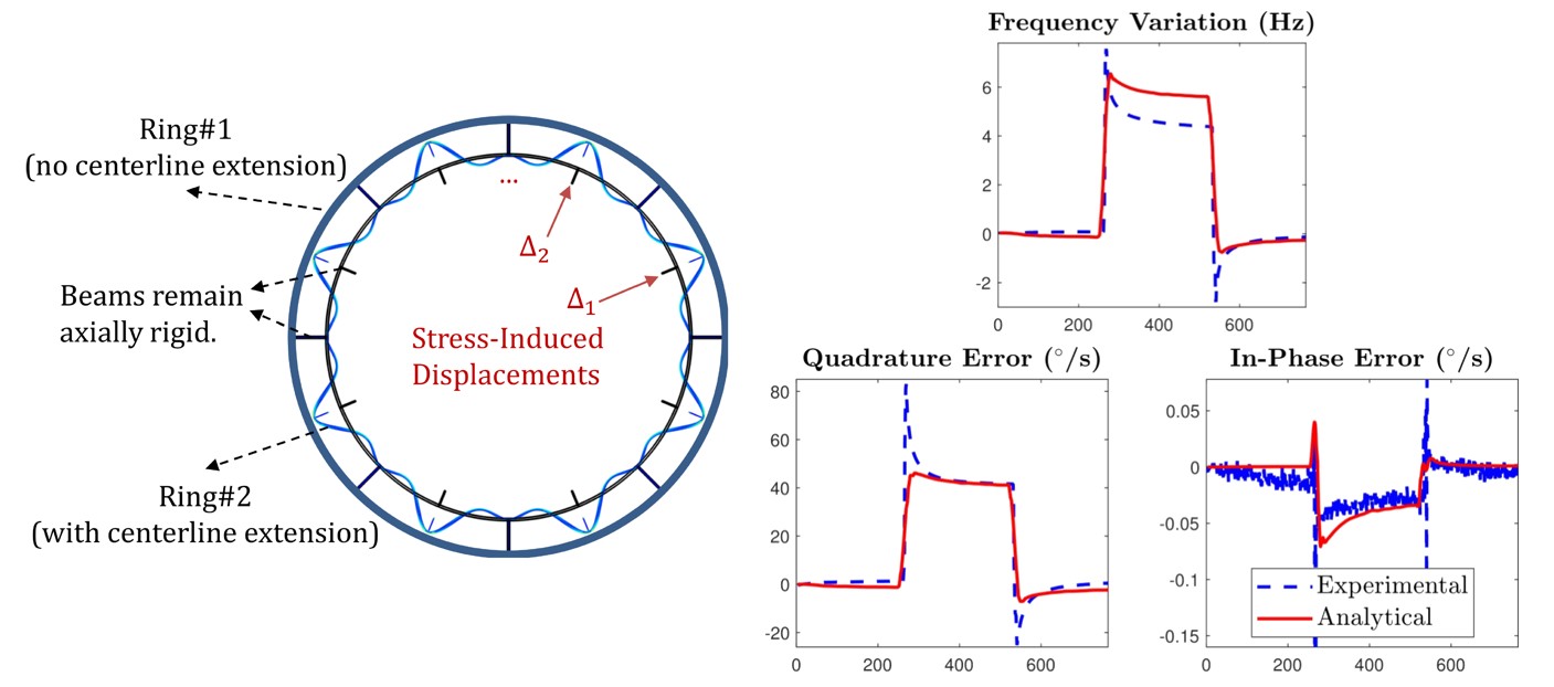
We can analytically predict the stress effects on the gyroscope.
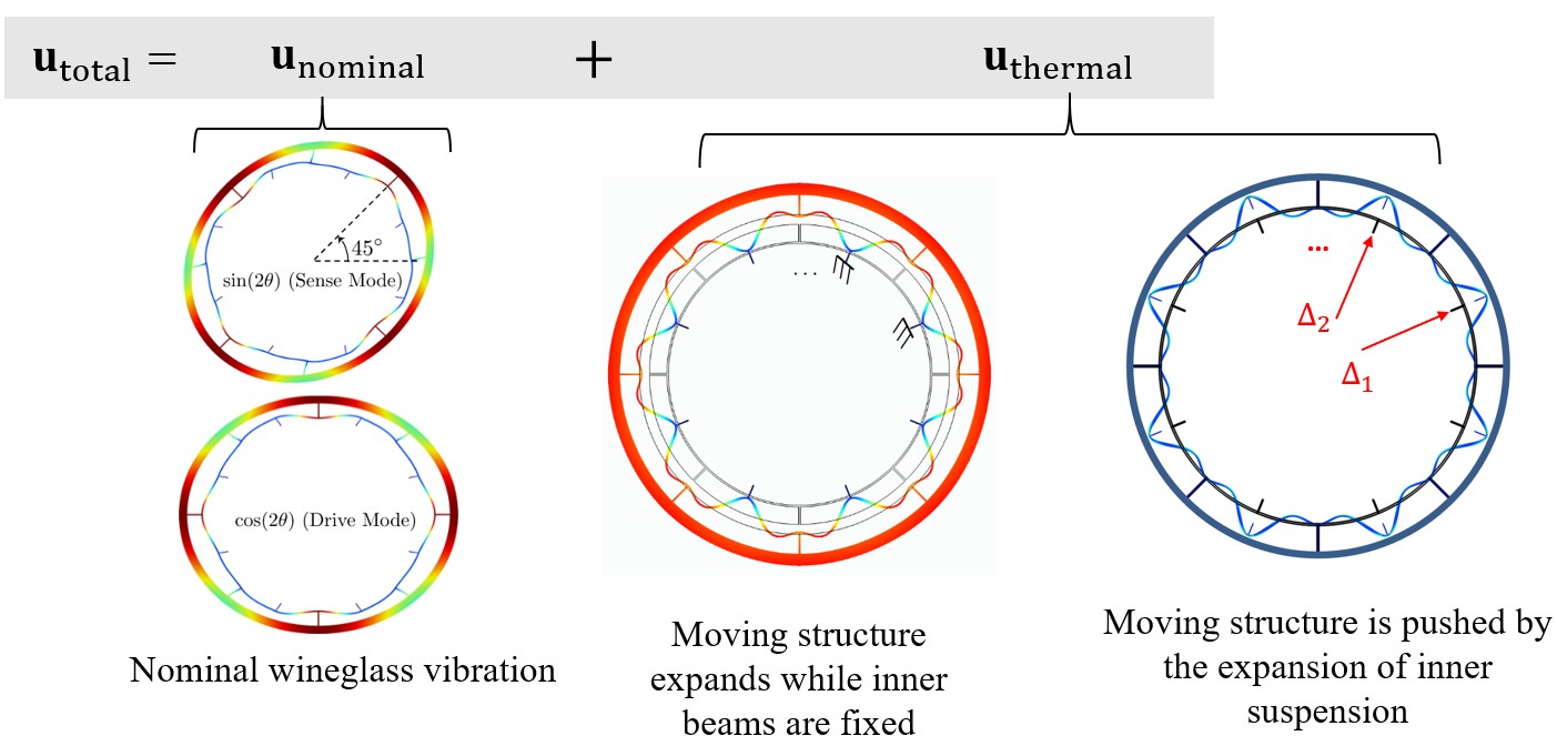
Temperature effects can also be modeled by using superposition. We superimpose the temperature-induced slow-time-scale variations onto the nominal vibration by accounting for stress and material property changes with temperature.
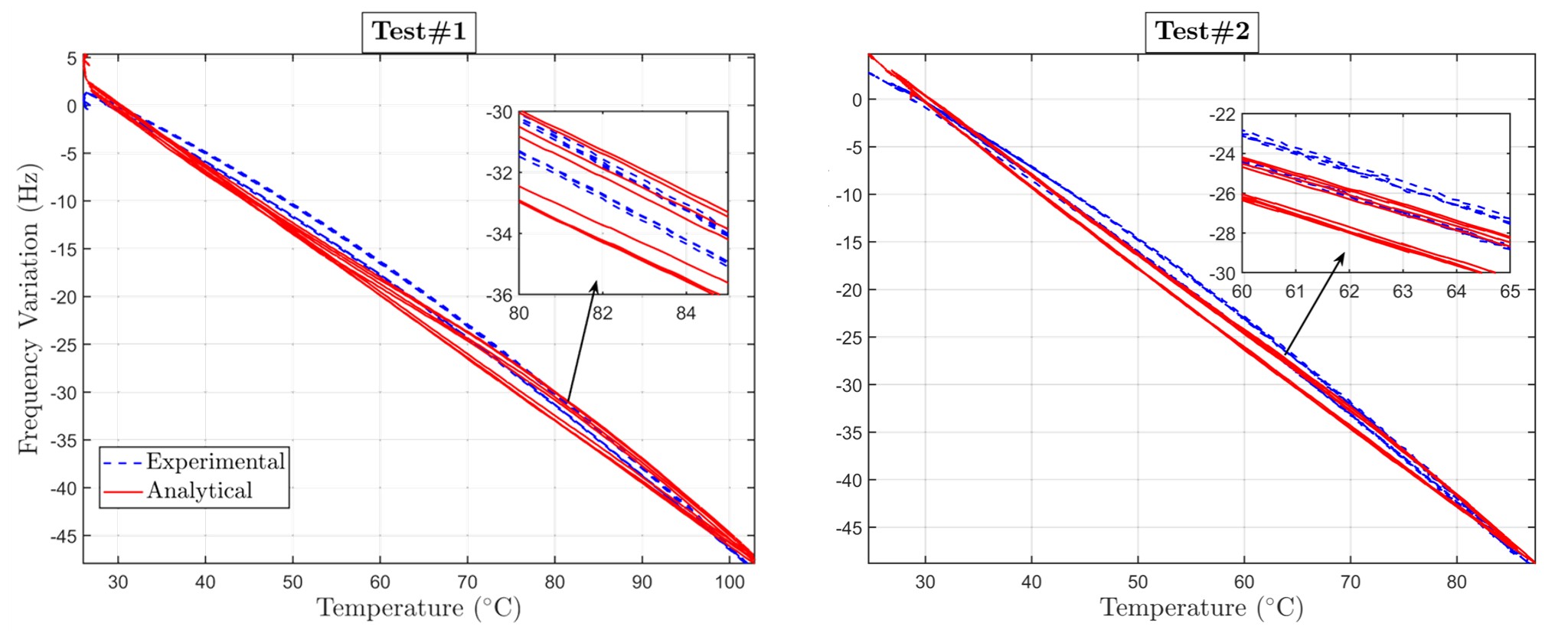
And successfully predict the gyroscope frequencies over temperature.
Evolution of 2-D stress over temperature within the ring gyroscope, calculated with our strain interpolation algorithm
The conflict strain and displacement captured by the stress sensors, which is inhomogeneous and causes unpredictable gyroscope behaviour. Measuring these strains enables a no-drift gyroscope.
Total strain and displacement (thermal expansion + conflict strain), which is mostly uniform. The nonuniformity of these fields is plotted on the left.