Universal Gas Sensing with Acoustic Coupling in a Cavity
This project has received funding from the European Union’s Horizon 2020 research and innovation programme under the Marie Skłodowska-Curie grant agreement No 101038092.
With current gas sensing technologies, sensors have to be developed individually for each gas under test. Most sensors available today rely on one of two techniques:
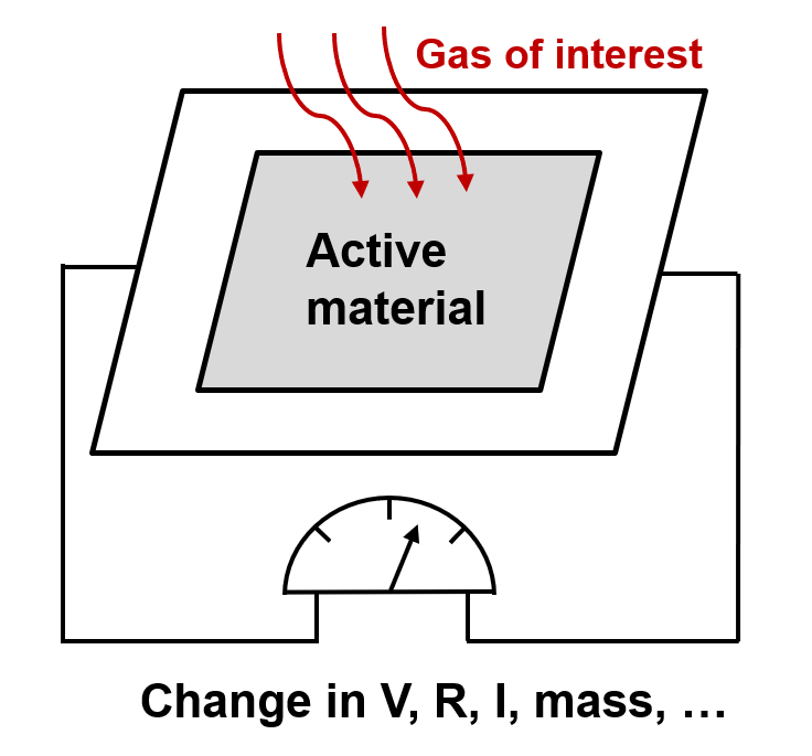
Chemical sensing: The gas of interest is passed over a substrate which reacts selectively with one or multiple types of gas. An electric current results which can be amplified to yield the result. Among chemical sensor types are metal oxide semiconductor, polymers and carbon nanotube sensors.
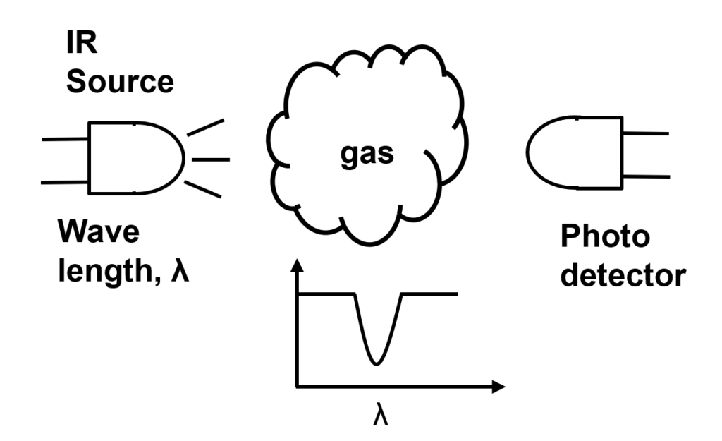
Infrared sensing: Used primarily for CO2 sensing, a beam of infrared light is passed through a chamber holding the gas of interest. The wavelength is selected to be absorbed by the target gas, therefore the output intensity is proportional to the concentration of gas in the measurement chamber. The nondispersive IR method uses this technique.
Acoustic Gas Sensing Concept
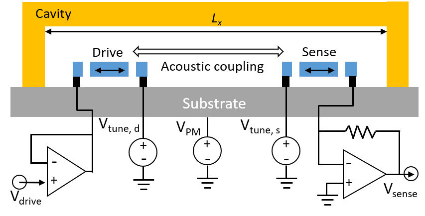
We propose an acoustic gas sensing concept that can be independent of material, allowing the detection of multiple gas types with one sensor. Our sensor technology relies on in-plane resonators and a simple rectangular cavity which are both easier and cheaper to fabricate than the alternatives. Figure 1 shows the proposed concept. Two in-plane resonators, are coupled through the acoustic resonance of the cavity.
The speed of sound in each gas can be expressed by c_{gas} = \sqrt{\frac{\gamma \cdot k \cdot T}{m}}
where \gamma is the adiabatic index, k is Boltzmann’s constant, T is the temperature in Kelvin, and m is the mass of a single molecule of gas. For most gases \gamma has a unique value around 1.4 and can be assumed as a constant. The remaining variables are temperature and the mass of each gas molecule. Temperature effects can be highly suppressed with a separate measurement and calibration step.
Measuring the speed of sound in a compact and small footprint can provide information about the gas content. In addition, gas viscosity can be measured through the damping of the system. The gas selectivity can be improved by utilizing the speed of sound and viscosity. Resonance based measurements provide high SNR. We propose to use the acoustic resonance of a cavity. One in-plane resonator (drive) excites the acoustic resonance of the cavity, and another in-plane resonator detects the cavity resonance.
Figure 1: Proposed gas sensor concept, in-plane MEMS resonators are coupled through the acoustic resonance of the cavity.
The acoustic resonance frequency of the cavity depends on c_{gas} and cavity dimensions:
where l,m,n are nonnegative integers. The cavity has multiple harmonics, we focus on f_{100} to show the proof of concept. The goal is to match the resonance frequency of drive and sense resonators to the fundamental cavity acoustic resonance.
Device description
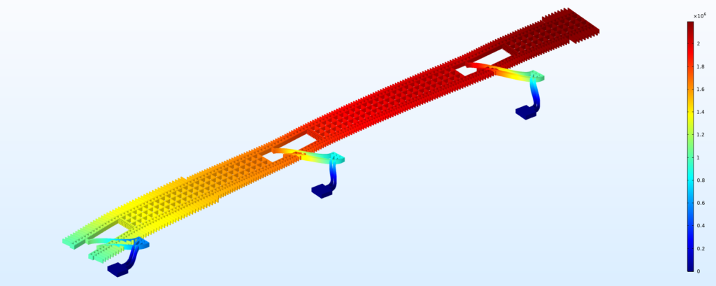
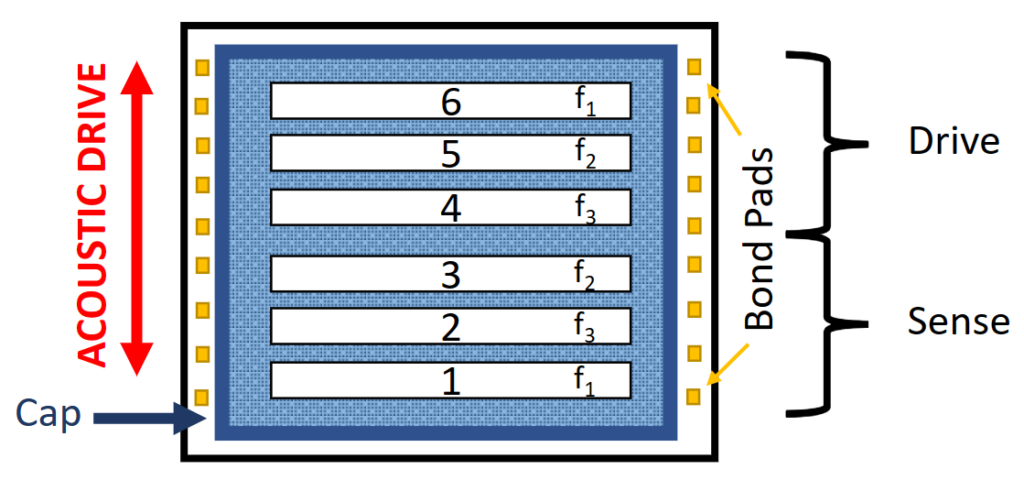
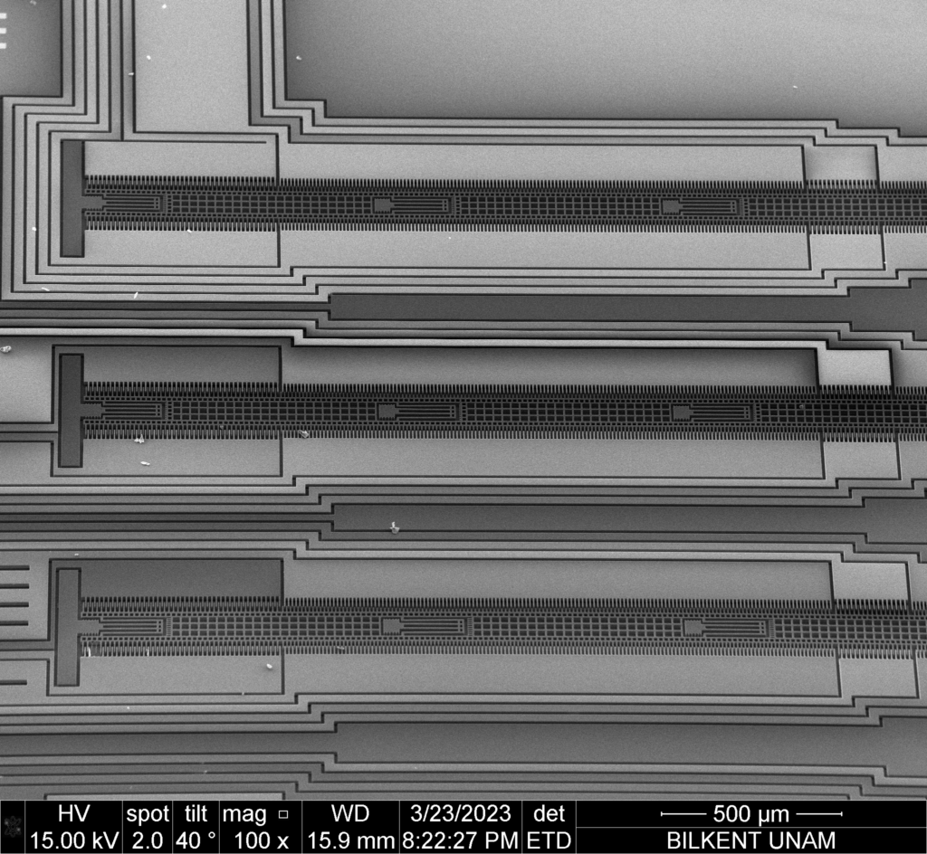
Assuming a cavity with L_{X}=5mm and c_{gas}=340 m/s, f_{100}=34kHz. We designed long and narrow resonators to excite and sense the acoustic resonance while minimally disturbing the cavity acoustics. Figure 2 shows the mode shape of the device. Given the fabrication tolerances, frequency tuning is required for the in-plane resonators. We located 3 drive and 3 sense resonators spanning a total of ~6kHz, each resonator spans ~2kHz. Figure 3 summarizes the overall device structure. We have 6 resonators in the cavity to make sure we can match the acoustic cavity resonance. Figure 4 shows the SEM image of a fabricated device, only 3 resonators are shown in the image.
Figure 2: FEM analysis showing the mode shape of the device
Figure 3: Picture summarizing the overall device structure
Figure 4: SEM image of the fabricated device, 3 resonators shown.
The devices are fabricated with an in-house SOI-MEMS process at Bilkent UNAM. The device, oxide, and handle layer thicknesses are 15 \mathrm{\mu m}, 2 \mathrm{\mu m}, and 600 \mathrm{\mu m} respectively. The device layer is highly conductive <100> Silicon.
Cr/Au is deposited and patterned with wet etch for wirebonding pads.
The device layer is formed with DRIE where SOI oxide acts as an etch-stop layer
The devices are released in buffered HF
The released dies are dried in a critical point dryer (CPD
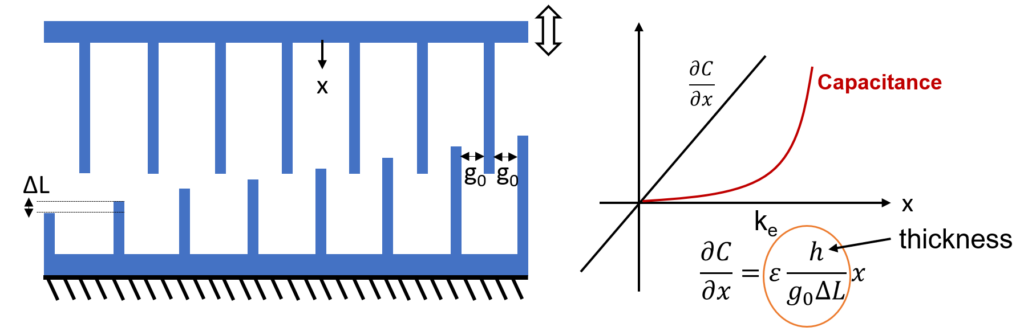
We excite the acoustic resonance with an in-plane resonator. High displacement of the MEMS resonator would result in stronger acoustic cavity resonance and better gas sensitivity. At the same time, the MEMS resonator should match the cavity resonance, which cannot be electrically tuned. Parallel plate capacitors can tune the MEMS resonator frequency but become highly nonlinear at high displacements. We designed length tapered frequency tuning combs that are fundamentally linear. Figure 5 summarizes the concept. As the fingers engage, the rate of capacitance change (dC/dx) increases linearly. dC/dx acts as an electrostatic spring that softens the mechanical spring of the MEMS resonator. Unlike parallel plate capacitors, length tapered combs do not suffer from nonlinearity as the displacement increases. They have practically unlimited displacement. We designed the lenght tapered combs for 10 mathrm{mu m} displacement.
Figure 5: Length tapered frequency tuning combs, as fingers engage the rate of capacitance change (dC/dx) increases linearly.
Experimental Results
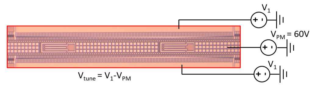
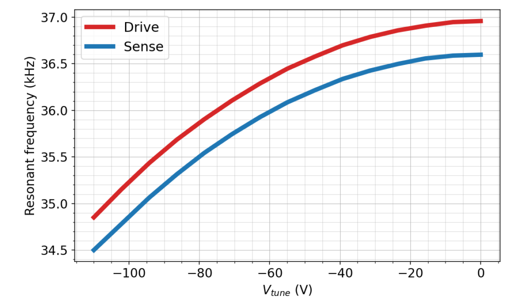
We will first report the performance of the length tapered frequency tuning combs. Figure 6 presents the optical image of the frequency tuning combs and the test configuration. Proof mass voltage (VPM) of 60V is applied to the movable mass and tuning voltage (V1) is applied to the stators. Figure 7 shows the tuning curves for the drive and sense resonators. We picked resonator 3 and 5 as the sense and drive resonators, respectively. Going negative for V1 maximizes the tuning range. 2kHz tuning range is obtained for the drive and sense resonators. The frequency tuning is directly related with V2tune. We also measured the speed of sound ( c_{gas} ) as 343m/s with an Arduino bases setup and commercially available ultrasonic sensors at room temperature. So we picked a cavity size with L_{X}=4.8mm that results in f_{100}=35.7kHz that is within the runing range of the drive and sense resonators.
Figure 6: Test configuration for the frequency tuning combs.
Figure 7: Tuning curves for the drive and sense resonators.
We carried our experiments with frequency sweeps with and without the cap to demonstrate the acoustic coupling between the drive and sense resonators. Figure 8 shows the test PCB, MEMS device with the Silicon cap and a cartoon summarizing the test conditions. The MEMS device is mounted to a 44-pin ceramic LCC (leadless chip carrier) which is then soldered to a duaghter board. The daughter board is connected to the main PCB housing the electronics. The silicon cap on the MEMS sensor is glued with epoxy, and electrically isolated with a layer of photoresist. As shown in Figure 1 there are three resonators in the proposed system, i.e. drive, sense, and the acoustic cavity. We can electrically tune the frequency of drive and sense resonators. We automated out setup such that it systematically tunes the drive and sense resonators and records the frequency sweep.
Figure 8: The test PCB, MEMS device with the Silicon cap, and a cartoon summarizing the operation.
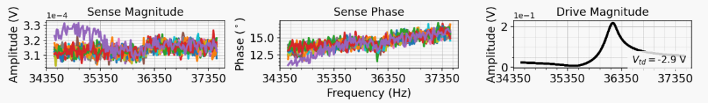
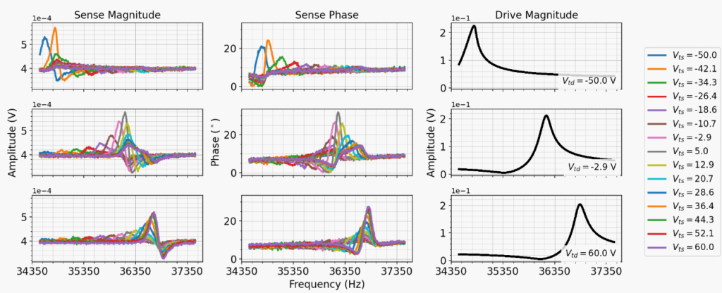
We ran our experiments by only driving the drive resonator and recording the frequency response of the drive and sense resonators for various tuning voltages on the drive and sense resonators. Without the cap on the MEMS die, we do not expect to see significant coupling from the drive to sense resonator. We expect to see drive to sense coupling with the cap through cavity acoustic resonance when the frequencies of the drive, sense and cavity resonance match. Figure 9 and 10 show the sense magnitude, phase and drive magnitude w.r.t. frequency without and with cap on the MEMS die, respectively. Only drive resonator is driven that exhibits a strong response. The sense resonator does not show any significant coupling without the cap, only the response at the maximal coupling (Vtd: Drive freq. tuning voltage and Vts: sense freq. tuning voltage) is plotted.
With the cap on the MEMS die a clear sense response is observed (Figure 10). In each row drive frequency is constant and the sense frequency is swept. The sense response peaks and then reduces as it is detuned. Since the acoustic cavity will exhibit second-order response the maximal drive to sense coupling occurs when the three frequencies (drive, sense, and acoustic) match. The acoustic coupling between the drive and sense resonators depends on the gas concentration, and can be employed as a gas sensor with control electronics.
Figure 9: Sense magnitude, phase and drive magnitude without the cap on the MEMS die. Only drive resonator is driven and no significant response is observed on the sense mode.
Figure 10: Sense magnitude, phase and drive magnitude w.r.t frequency with the cap on the MEMS die. Only drive resonator is driven, and a clear respose is observed on the sense mode. Varying the drive and sense resonator frequencies change the coupling proving the acoustic cavity coupling between the resonators.
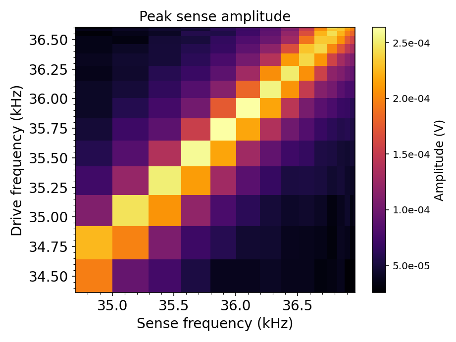
Figure 11 presents a comprehensive look at our experiments with the cap. For each sweep we find the maximum sense voltage and plot it with the corresponding drive and sense resonance frequency. The sense voltage increases towards the diagonal where the drive and sense frequencies are the same, and the maximum occurs ~36kHz, where the cavity acoustic resonance matches the MEMS frequencies. Moving along the diagonal from the 36kHz the sense voltage decreases, proving the acoustic coupling between the drive and sense resonators. The second order cavity acoustic response can be observed along the diagonal in Figure 11.
Figure 11: The peak sense amplitude at each frequency sweep. Sense amplitude increases when the drive and sense frequencies are close. And when the cavity acoustic frequency matches (~36kHz) maximal coupling occurs proving the acoustic coupling.
Summary
We demonstrated that two in-plane resonators could be coupled through the acoustic resonance of the cavity. The acoustic coupling is an indication of the gas content and along with damping (the rate acoustic resonance vanishes) could be used as a gas sensor. The proof of concept has been shown and future work will focus on building electronics to lock the in-plane resonators to the acoustic cavity resonance and gas tests. The main advantage of the proposed method is its simplicity and it can be used to detect any gas with proper calibration.